Overhead power line
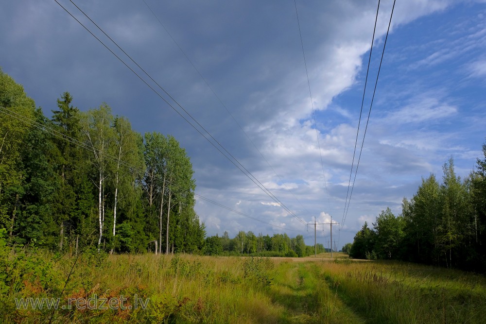
An overhead power line is a structure used in electric power transmission and distribution to transmit electrical energy along large distances. It consists of one or more conductors (commonly multiples of three) suspended by towers or poles. Since most of the insulation is provided by air, overhead power lines are generally the lowest-cost method of power transmission for large quantities of electric energy.
Construction
Towers for support of the lines are made of wood (as-grown or laminated), steel or aluminum (either lattice structures or tubular poles), concrete, and occasionally reinforced plastics. The bare wire conductors on the line are generally made of aluminum (either plain or reinforced with steel, or composite materials such as carbon and glass fiber), though some copper wires are used in medium-voltage distribution and low-voltage connections to customer premises. A major goal of overhead power line design is to maintain adequate clearance between energized conductors and the ground so as to prevent dangerous contact with the line, and to provide reliable support for the conductors, resilience to storms, ice loads, earthquakes and other potential damage causes. Today overhead lines are routinely operated at voltages exceeding 765,000 volts between conductors, with even higher voltages possible in some cases.
Classification by operating voltage
Overhead power transmission lines are classified in the electrical power industry by the range of voltages:
- Low voltage (LV) – less than 1000 volts, used for connection between a residential or small commercial customer and the utility.
- Medium voltage (MV; distribution) – between 1000 volts (1 kV) and 69 kV, used for distribution in urban and rural areas.
- High voltage (HV; subtransmission less than 100 kV; subtransmission or transmission at voltages such as 115 kV and 138 kV), used for sub-transmission and transmission of bulk quantities of electric power and connection to very large consumers.
- Extra high voltage (EHV; transmission) – from 345 kV, up to about 800 kV,[2][page needed] used for long distance, very high power transmission.
- Ultra high voltage (UHV) – higher than 800 kV. The Financial Times reported UHV lines are a "game changer", making a global electricity grid potentially feasible. StateGrid said that compared to conventional lines, UHV enables the transmission of five time more power, over six times the distance.
Structures
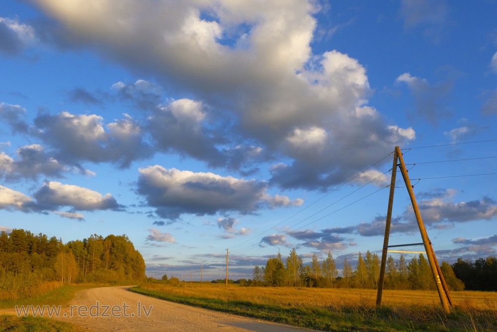
Structures for overhead lines take a variety of shapes depending on the type of line. Structures may be as simple as wood poles directly set in the earth, carrying one or more cross-arm beams to support conductors, or "armless" construction with conductors supported on insulators attached to the side of the pole. Tubular steel poles are typically used in urban areas. High-voltage lines are often carried on lattice-type steel towers or pylons. For remote areas, aluminum towers may be placed by helicopters. Concrete poles have also been used. Poles made of reinforced plastics are also available, but their high cost restricts application.
Each structure must be designed for the loads imposed on it by the conductors. The weight of the conductor must be supported, as well as dynamic loads due to wind and ice accumulation, and effects of vibration. Where conductors are in a straight line, towers need only resist the weight since the tension in the conductors approximately balances with no resultant force on the structure. Flexible conductors supported at their ends approximate the form of a catenary, and much of the analysis for construction of transmission lines relies on the properties of this form.
A large transmission line project may have several types of towers, with "tangent" ("suspension" or "line" towers, UK) towers intended for most positions and more heavily constructed towers used for turning the line through an angle, dead-ending (terminating) a line, or for important river or road crossings. Depending on the design criteria for a particular line, semi-flexible type structures may rely on the weight of the conductors to be balanced on both sides of each tower. More rigid structures may be intended to remain standing even if one or more conductors is broken. Such structures may be installed at intervals in power lines to limit the scale of cascading tower failures.
Foundations for tower structures may be large and costly, particularly if the ground conditions are poor, such as in wetlands. Each structure may be stabilized considerably by the use of guy wires to counteract some of the forces applied by the conductors.
Power lines and supporting structures can be a form of visual pollution. In some cases the lines are buried to avoid this, but this "undergrounding" is more expensive and therefore not common.
For a single wood utility pole structure, a pole is placed in the ground, then three crossarms extend from this, either staggered or all to one side. The insulators are attached to the crossarms. For an "H"-type wood pole structure, two poles are placed in the ground, then a crossbar is placed on top of these, extending to both sides. The insulators are attached at the ends and in the middle. Lattice tower structures have two common forms. One has a pyramidal base, then a vertical section, where three crossarms extend out, typically staggered. The strain insulators are attached to the crossarms. Another has a pyramidal base, which extends to four support points. On top of this a horizontal truss-like structure is placed.
A grounded wire is sometimes strung along the tops of the towers to provide lightning protection. An optical ground wire is a more advanced version with embedded optical fibers for communication. Overhead wire markers can be mounted on the ground wire to meet International Civil Aviation Organization recommendations. Some markers include flashing lamps for night-time warning.
Circuits
A single-circuit transmission line carries conductors for only one circuit. For a three-phase system, this implies that each tower supports three conductors.
A double-circuit transmission line has two circuits. For three-phase systems, each tower supports and insulates six conductors. Single phase AC-power lines as used for traction current have four conductors for two circuits. Usually both circuits operate at the same voltage.
In HVDC systems typically two conductors are carried per line, but in rare cases only one pole of the system is carried on a set of towers.
In some countries like Germany most power lines with voltages above 100 kV are implemented as double, quadruple or in rare cases even hextuple power line as rights of way are rare. Sometimes all conductors are installed with the erection of the pylons; often some circuits are installed later. A disadvantage of double circuit transmission lines is that maintenance can be difficult, as either work in close proximity of high voltage or switch-off of two circuits is required. In case of failure, both systems can be affected.
The largest double-circuit transmission line is the Kita-Iwaki Powerline.
en.wikipedia.org